


 Dana on Data: The Missing AI-NPI Link
 Beyond Design: Key SI Considerations for High-speed PCB Design
 Elementary Mr. Watson: Ensuring a Smooth Handoff From PCB Design to Fabrication


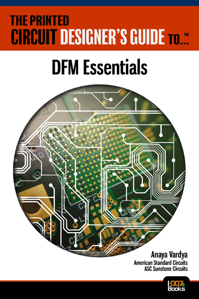
Book Excerpt: The Printed Circuit Designer’s Guide to... DFM Essentials, Ch. 1
October 25, 2024 | I-Connect007Estimated reading time: 1 minute
Excerpt from: The Printed Circuit Designer’s Guide to... DFM Essentials
By Anaya Vardya, American Standard Circuits / ASC Sunstone Circuits
Chapter 1: Materials
Standard Multilayer Materials
Most PCBs are manufactured using three basic materials: glass-reinforced epoxy laminate, prepreg, and copper foil. PCBs are constructed from three basic material types: copper foil, prepreg, and cores.
Copper foil: Sheets of copper foil are incorporated into the outer layer of the PCB, laminating it onto the prepreg to create the outer layers. Outer layers are generally constructed using ½-ounce copper or thicker depending on the design requirements. Internal layers are constructed with copper that is specified on the fabrication print. Half-ounce copper foil is commonly used for signal layers; 1 ounce for plane layers, and 2 ounce or greater for power planes where there is a high DC current. Other thicknesses may be used based on the design requirements.
Prepreg: This is a semi-cured glass resin material. The resin used for the FR-4 type materials is epoxy-based. There is no copper attached to this material.
Core: This is fully cured glass-resin material with copper laminated to both sides. This is typically used for internal layers. It is occasionally used for outer layers, but that is not a preferred construction method. A core is constructed from either one sheet of prepreg (single ply) or two or more sheets of prepreg, and two layers of copper foil. Single ply is considered the preferred core construction and has better dimensional stability.
High-frequency (RF/Microwave) Materials
High-frequency designs (1 GHz and up) require materials with closely controlled dielectric constants and dissipation factors. The FR-4 materials normally used for PCBs don’t have the desired controlled characteristics. The substrate materials used for high-frequency applications were originally based upon PTFE resin formulations that have the desired properties, i.e. dielectric constant (Dk) controlled to +/- 0.04 and dissipation factor (Df) to 0.0004. These values may vary somewhat depending on the material type and supplier. Today, there are a number of materials on the market that do not contain PTFE resin but still have controlled values that can be used for high-frequency applications.
Visit the I-Connect007 library to continue reading The Printed Circuit Designer’s Guide to... DFM Essentials.
Share on:


Suggested Items
AT&S Sets New Standards in the Recycling of Copper and Chemicals
03/25/2025 | AT&SAT&S has been working for years to reduce the ecological footprint of its production sites worldwide with a comprehensive sustainability strategy and considerable investments.
Empowering the Future of Advanced Computing and Connectivity: DuPont Unveils Innovative Advanced Circuit Materials in Shanghai
03/24/2025 | DuPontDuPont will showcase how we are shaping the next generation of electronics at the International Electronic Circuits (Shanghai) Exhibition 2025.
Just Because You Can, Doesn’t Mean You Should
03/20/2025 | Tony Plemel, Flexible Circuit TechnologiesDecisions are usually made by gathering information and differing opinions, then making the best choice based upon that information. The same process is used when designing flexible circuits and rigid-flex circuits. For example, when designing a flex circuit or rigid-flex circuit, we consider some basic factors.
ICT Spring Seminar: Nickel Not Welcome Here
03/12/2025 | Pete Starkey, I-Connect007After a miserable, dull, and damp English winter, a really pleasant nearly spring day with the sun shining and daffodils in bloom greeted delegates to the Institute of Circuit Technology Spring Seminar at Puckrup Hall near Tewkesbury, March 5, in Gloucestershire, UK.
Multicircuits Expands Capabilities with State-of-the-Art Automated Copper Via Fill Process
03/10/2025 | MulticircuitsMike Thiel, president of Multicircuits, a leading provider of high-reliability printed circuit boards, has announced the addition of a state-of-the-art automated copper via fill process to their advanced manufacturing capabilities. This strategic investment enhances the company’s ability to deliver cutting-edge solutions for demanding industries, including aerospace, defense, medical, and high-speed telecommunications.